The Old CATV Equipment Museum
Amplifiers
Vacuum Tube - Jerrold Electronics Corp.
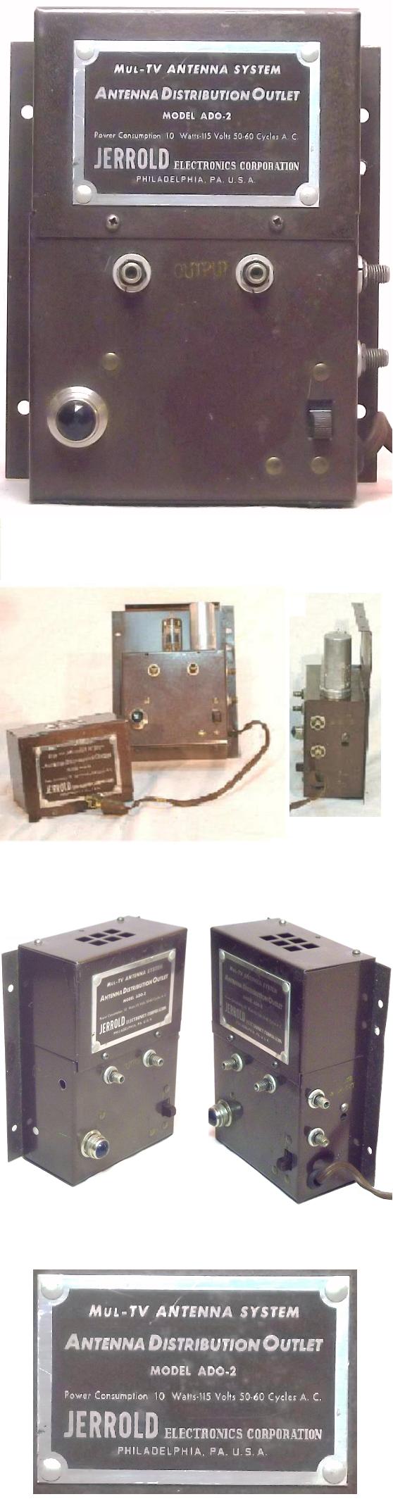
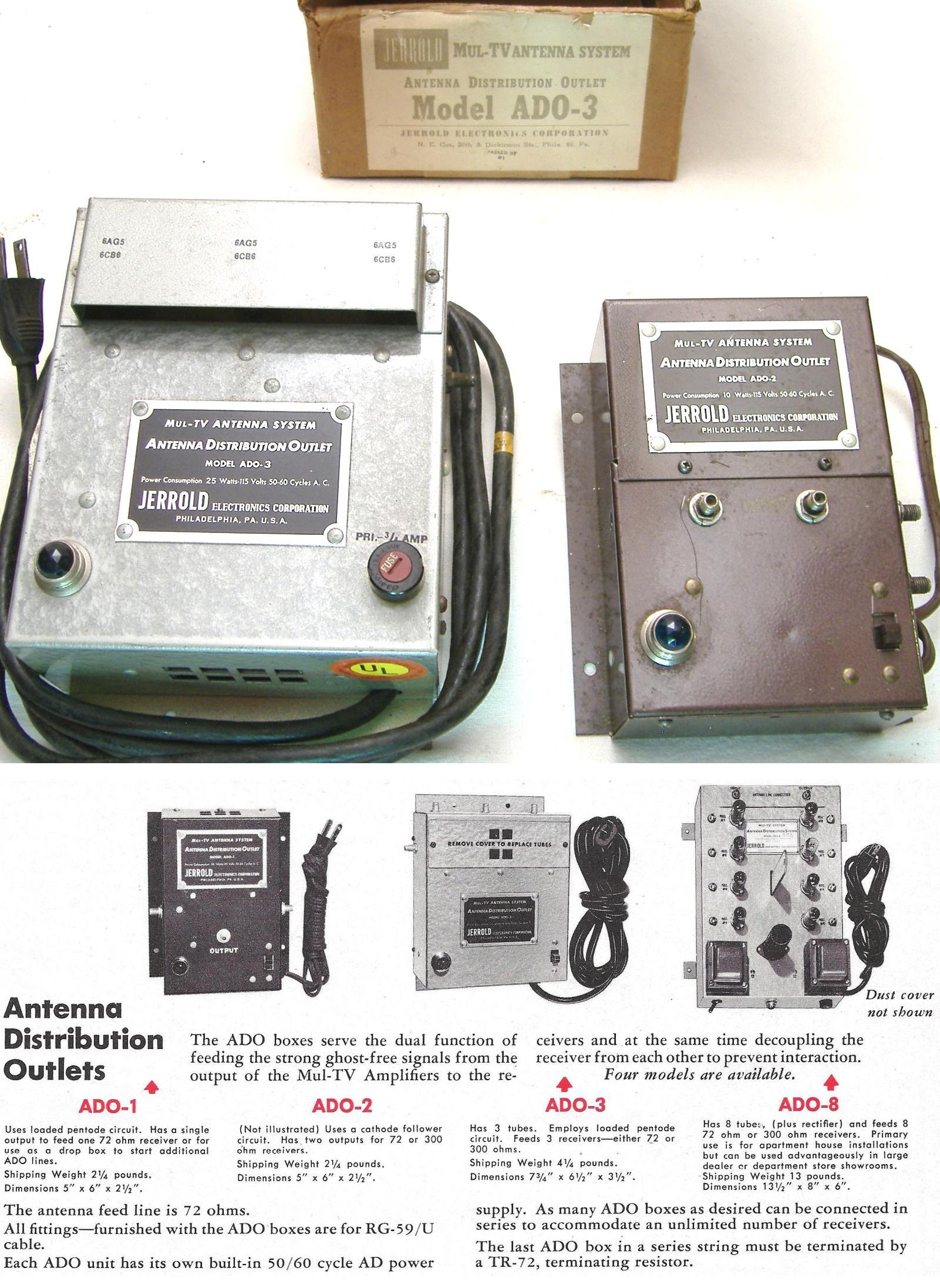
Jerrold Mul-TV Antenna Systems ADO-2
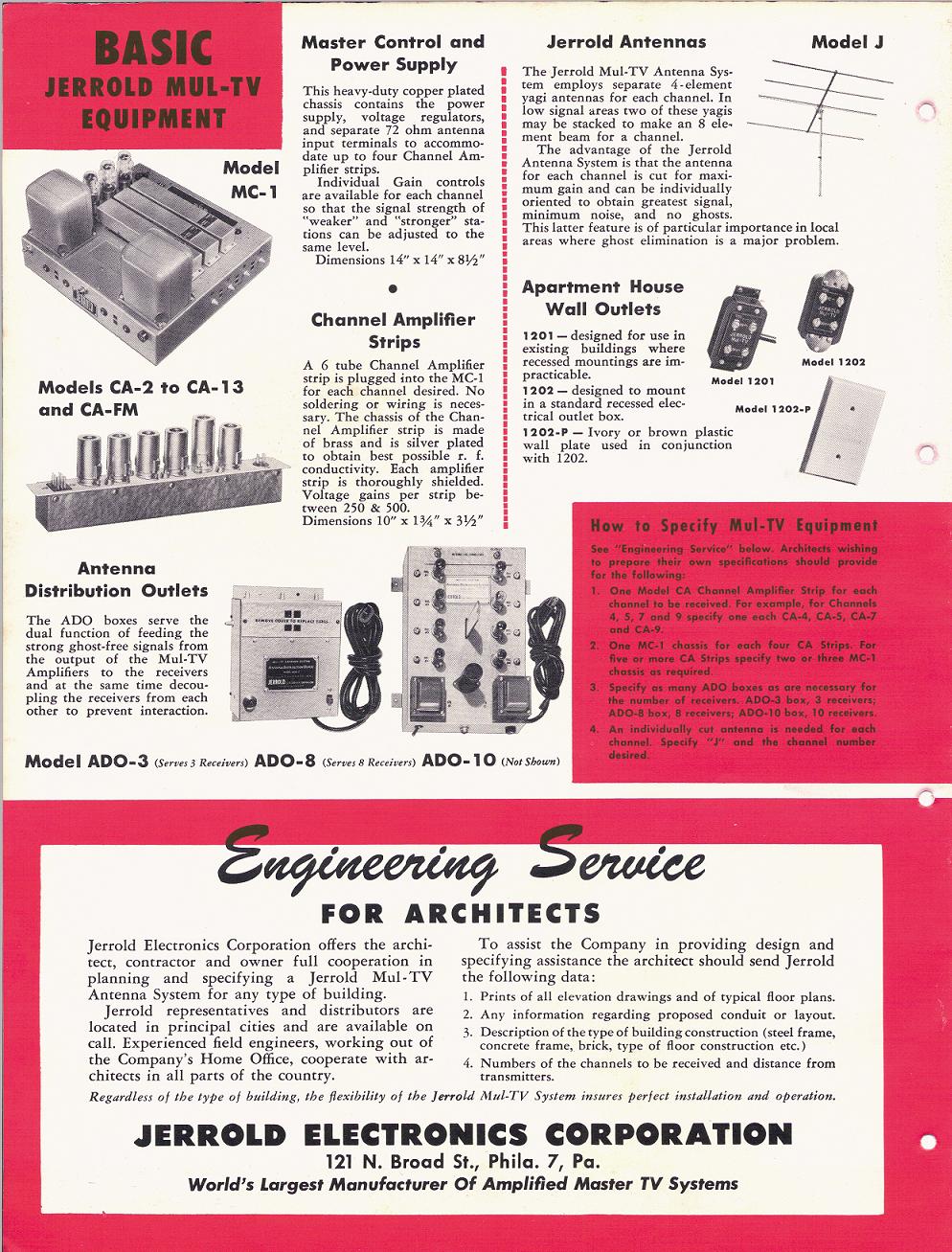
The first Broadband Television System Equipment Jerrold built was
the Mul-TVseries. The first Amplifier in the series was the
Antenna Distributed Outlet or the ADO Box as it was commonly called.
Although the initial ADO 2 was not considered a very stable Amplifier
its successor ADO Boxes (The ADO-3, ADO-8 and ADO-10) were
much better devices and widely used in MDU type applications and
were installed in locations like Hotels, TV Showrooms, Apartment
Complexes and Hospitals.
 | | Photo:Lew Chandler |
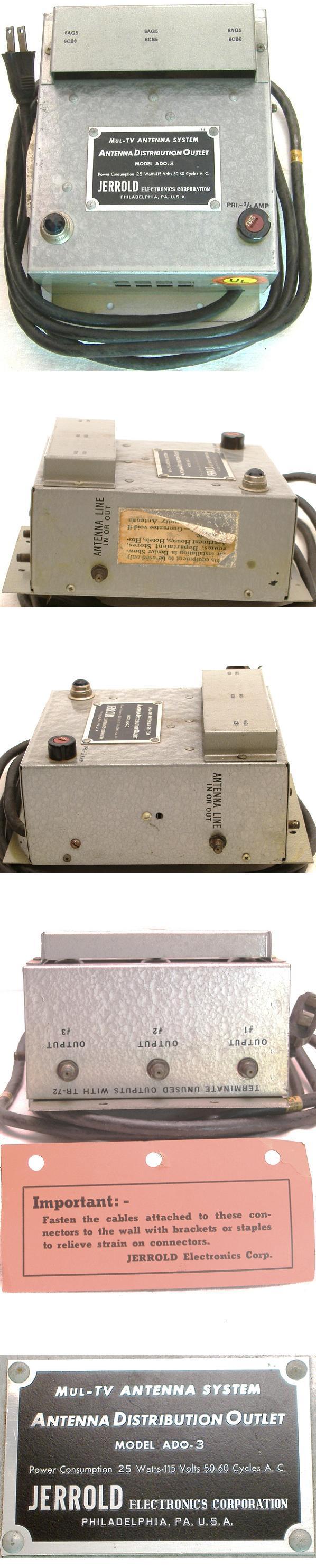
Jerrold Mul-TV Antenna Distribution Outlets
ADO-3 and ADO-2 Comparison
Jerrold Mul-TV Antenna Systems ADO-3
 | | Photo:Lew Chandler |
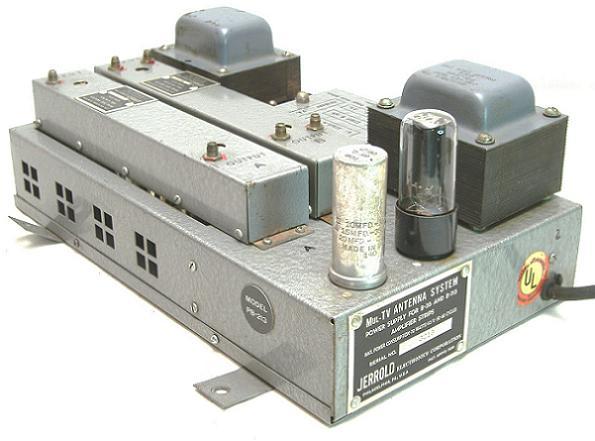
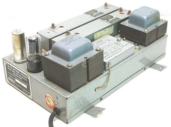
Jerrold Mul-TV All Band Amplifier
Model PB-213
Donated by Graham Stubbs
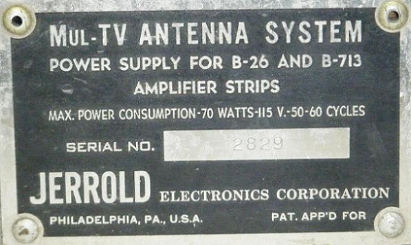
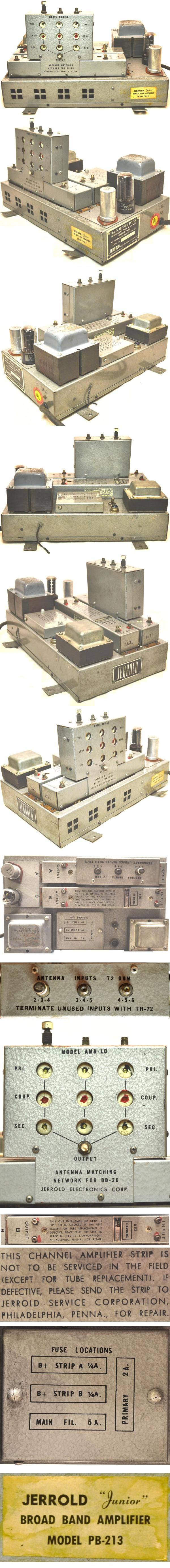
The Jerrold Mul-TV System included an Amplifier for the received signals
at the antenna location or for amplifying signals at certain locations in
the main cable line.
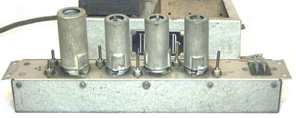
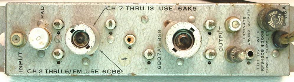
The amp was a Mixer Amp configuration and consisted of 1, 2 or
3 strip amplifiers (single channel amps) and a housing which supplied
the power for the strip amps, additional shielding for better RF
performance and protected the amplifiers vacuum tubes.
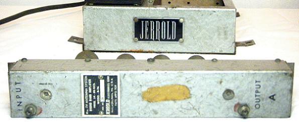
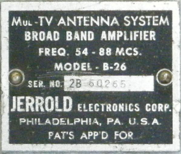
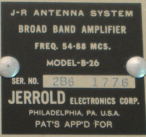
The strip amps were not channel specific but were band specific. There
was the Model B-26 which amplified channel 2 through 6 in the low
band and the Model B213 which amplified channel 7 through 13 in the
high band. The channels were either separated at the input or combined
at the output using a LHS76 diplexer for the low and high bands or an
AMN Low or AMN Hi channel combining/separating network for
individual channels.
Although Jerrold recommended using a strip amp for only one channel it
was common practice to input 2 channels as long as the channels could
be placed far apart in the spectrum
As an example it was possible to Combine Channel 2 and 4,Channel 2
and 5 or Channel 3 and 5. Amplifying adjacent channels like Channel 2
and 3 or 3 and 4 would cause them to interfere with each other.
. If the channels were not spaced properly from the source a channel
converter was needed to change the channel assignment. In the early
days operators would use homemade oscillator configurations to alter
the frequency of the incoming channel.
 | | Photo:Lew Chandler |
 | | Photo:Lew Chandler |
 | | Photo:Lew Chandler |
Jerrold Mul-TV Low Band Strip Amplifier
Model B-26
 | | Photo:Lew Chandler |
 | | Photo:Lew Chandler |
 | | Photo:Lew Chandler |
Jerrold Mul-TV Systems Broadband Amplifier
Model "Junior" PB-213
 | | Photo:Lew Chandler |
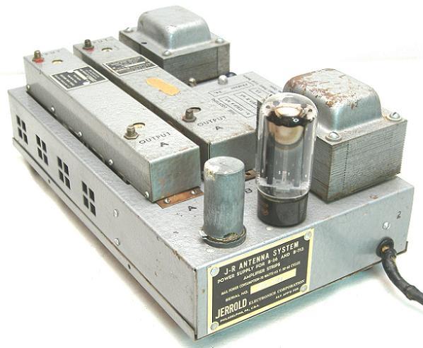
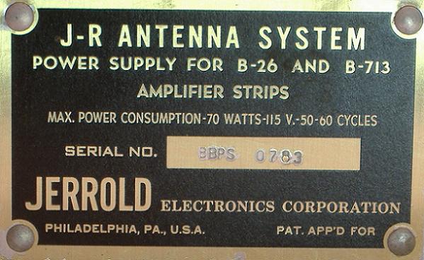
Jerrold JR Antenna Systems Amplifier
Model PB-213
In the early 1950's Jerrold Marketed the Mul-TV series under the name
of JR Antenna Systems. The JR stood for Job Rated.
 | | Photo:Lew Chandler |
 | | Photo:Lew Chandler |
 | | Photo:Lew Chandler |
Jerrold Electronics JR (Job Rated) System
Caution - long downoad time due to large file size
Jerrold Electronics JR System Instruction Manual 1952
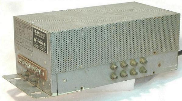
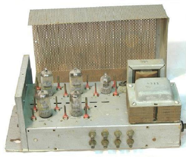
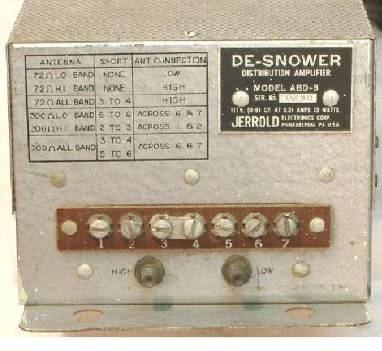
Jerrold De-Snower All Band Distribution Amplifier
Model ABD-8
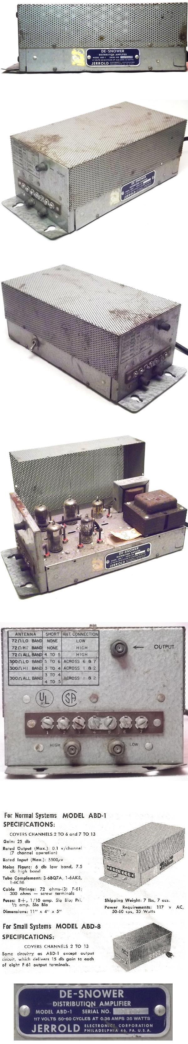
The next generation Jerrold Distribution amplifier was the ABD or All
Band Distribution Amplifier. There were several configurations which,
like the ADO box, provided various output port configurations. The
first model shown is an ABD-8 which has 8 output ports to serve 8
service locations. The next model is an ABD-1. There was also a
Model DSA-132 version which was adapted as a mast mounted
broadband antenna pre-amp.
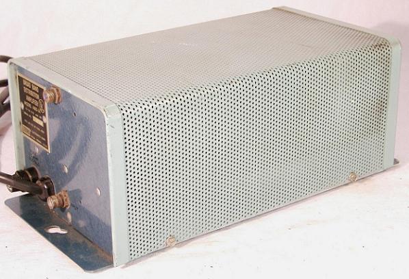
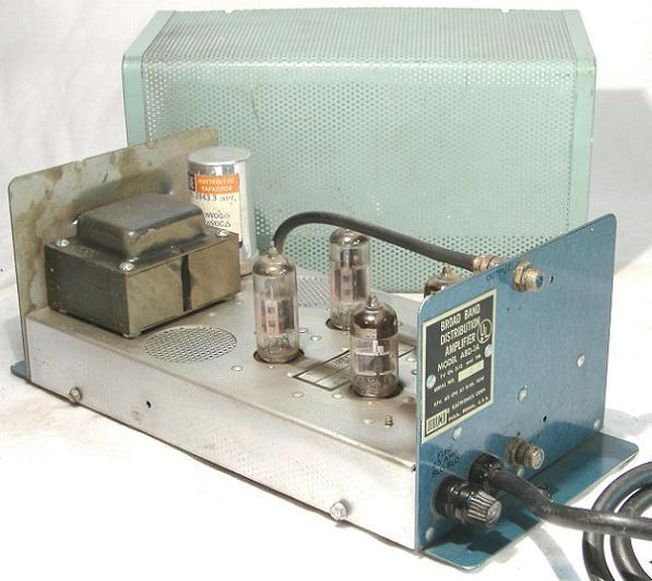
The ABD was a very successful design and it was subsequently
upgraded to the ABD-1A. Production continued into the 1960's.
 | | Photo:Lew Chandler |
 | | Photo:Lew Chandler |
 | | Photo:Lew Chandler |
Jerrold Electronics Instruction Sheet
Jerrold ABD-1 and ABD-8 All Band Distribution Amplifier 1957
Jerrold De-Snower All Band Distribution Amplifier
Model ABD-1
 | | Photo:Lew Chandler |
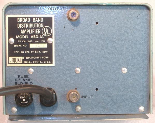
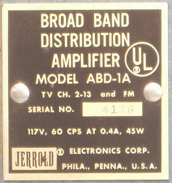
Jerrold Broad Band Distribution Amplifier
Model ABD-1A
 | | Photo:Lew Chandler |
 | | Photo:Lew Chandler |
 | | Photo:Lew Chandler |
 | | Photo:Lew Chandler |
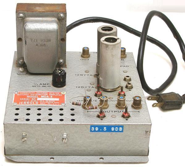
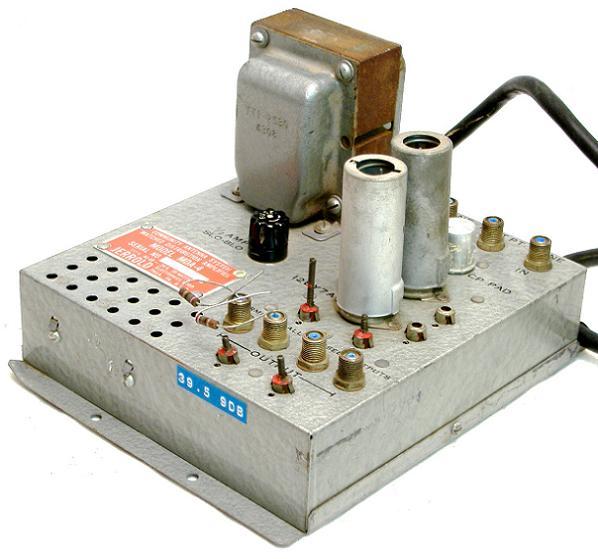
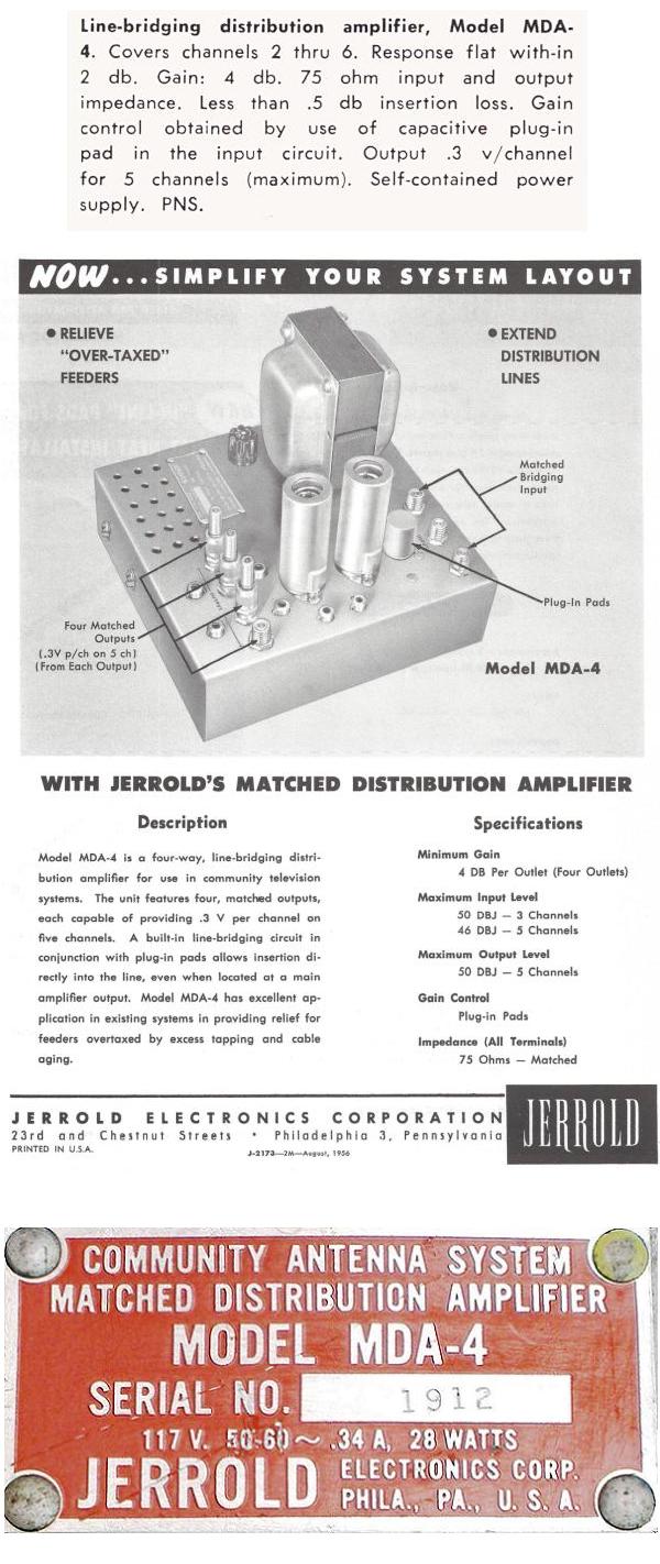
Jerrold Community Antenna Systems
Matched Distribution Amplifier
Model MDA-4
Donated by Graham Stubbs
As the technology grew and systems were being built to serve
communities Jerrold started the Community Antenna Systems line of
equipment. The Matched Distribution Amplifier was the recommended
line distribution amp in place of the Mul-TV ADO box. The MDA was
a low band amplifier used to amplify channels 2 through 6. High band
channels had to be converted to the low band spectrum at the Headend.
 | | Photo:Lew Chandler |
 | | Photo:Lew Chandler |
 | | Photo:Lew Chandler |
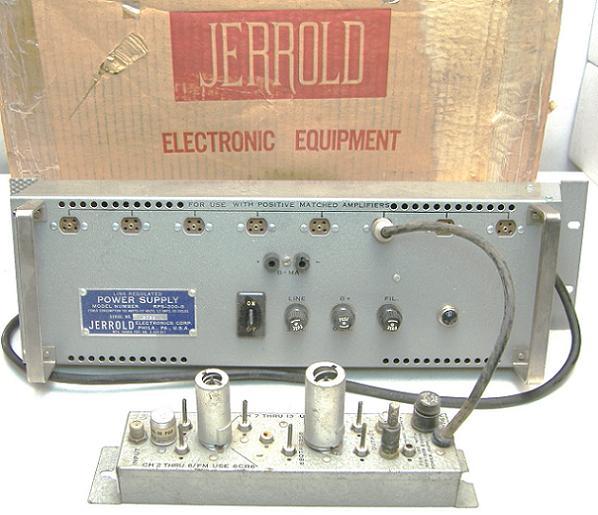
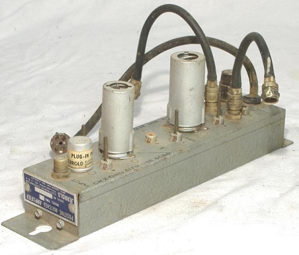
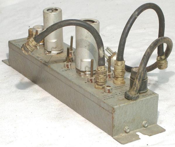
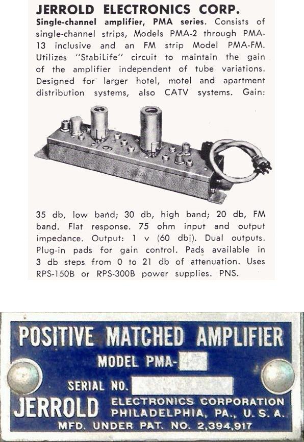
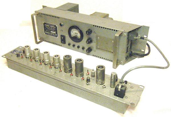
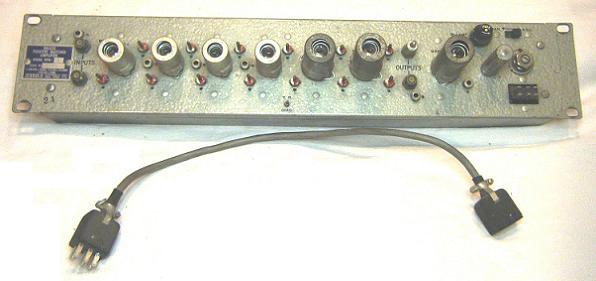
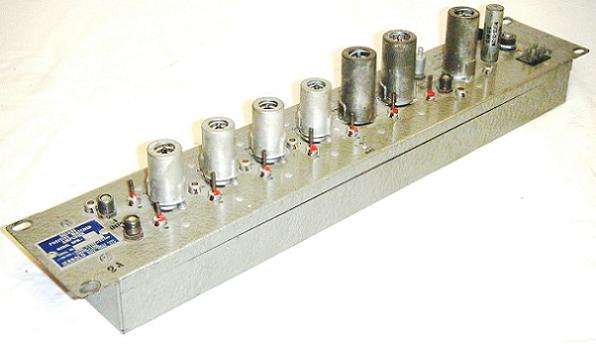
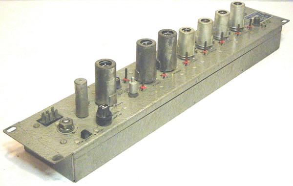
Jerrold Positive Matched Amplifier Single Channel Channel Amplifier
Model PMA-4
and Matching Power Supply Model RPS-300-B
Donated by Graham Stubbs
As the technology grew and systems were being built to serve communities
Jerrold started the Community Antenna Systems line of equipment.
The Matched Distribution Amplifier was the recommended line
distribution amp in place of the Mul-TV ADO box or the ABD All Band
Distribution Amplifier.
The MDA was a low band amplifier used to amplify channels 2 through 6.
In order to use high band channels (channels 7 through 13) they had to
be converted to the low band spectrum at the Headend. The Jerrold
Channel converter developed for this purpose was the WCON.
 | | Photo:Lew Chandler |
 | | Photo:Lew Chandler |
 | | Photo:Lew Chandler |
 | | Photo:Lew Chandler |
Jerrold Electronics Instruction Sheet
Jerrold PMA Positive Match Amplifier 1959
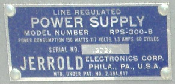
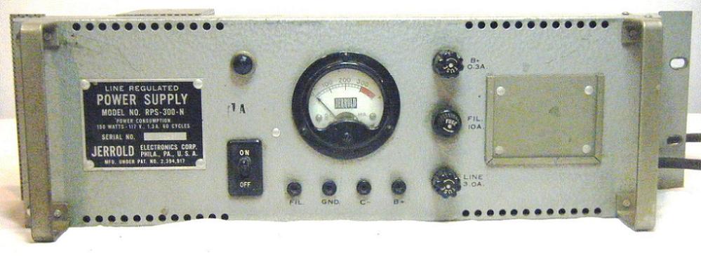
Jerrold Power Supply for the Positive Matched Amplifier Model
RPS-300-B
Donated by Graham Stubbs
 | | Photo:Lew Chandler |
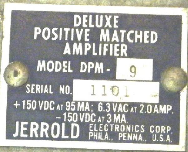
Jerrold Deluxe Positive Matched Amplifier
with Matching Power Supply
Model RPS-300-N
Donated by Kaz Majewski, of Centre TV, Wheeling West Virginia
The Deluxe Positive Matched (DPM) Amplifier met the same needs as
the PMA only for larger systems with longer main line cable runs and
a larger subscriber base.
 | | Photo:Lew Chandler |
 | | Photo:Lew Chandler |
 | | Photo:Lew Chandler |
 | | Photo:Lew Chandler |
 | | Photo:Lew Chandler |
Jerrold Electronics Instruction Sheet
Jerrold Delux Positive Matched Amplifier Model DPM 1958
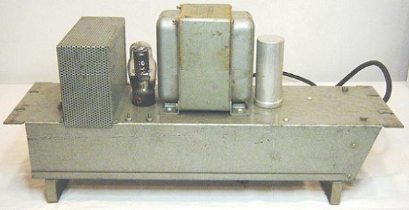
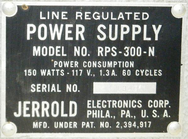
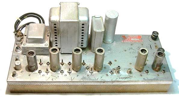
Jerrold Matching Power Supply for the Deluxe Positive Matched Amplifier
Model RPS-300-N
Donated by Kaz Majewski, of Centre TV, Wheeling West Virginia
 | | Photo:Lew Chandler |
 | | Photo:Lew Chandler |
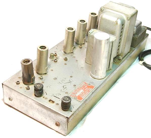
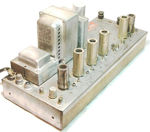
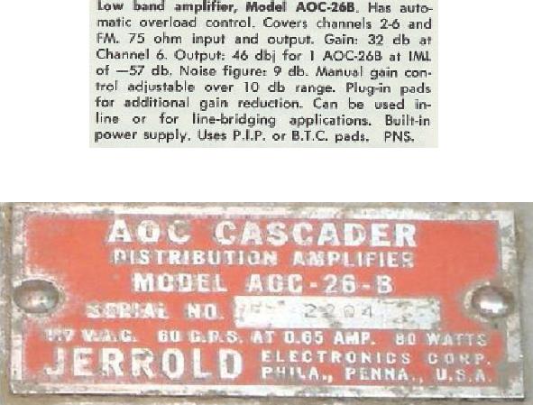
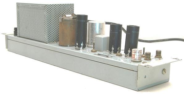
Jerrold AOC Cascader Distribution Amp
Model AOC-26-B
The next generation of Jerrold amplifiers that replaced the MDA series
was the Cascader series.
There were several new innovations in the Cascader Amplifiers which
included an AOC (Automatic Overload Control) circuit to automatically
adjust the output level to compensate for signal changes caused by
variations in temperature and a plug in pad to adjust the input signal for
optimum amplifier performance.
The AOC circuit was controlled by a Control Carrier Generator which
injected a reference carrier at the Headend. The AOC circuit monitored
the carrier and made the necessary adjustments when the level changed.
The AOC adjustment had 6dB of range and could either turn the
amplifier up 3 dB or down 3 dB. We know the AOC circuit as an AGC
(Automatic Gain Control) circuit today.
The AOC Cascader was a 5 channel amplifier capable of amplifying
channels in the low band (channels 2 through 6).
 | | Photo:Lew Chandler |
 | | Photo:Lew Chandler |
 | | Photo:Lew Chandler |
 | | Photo:Lew Chandler |
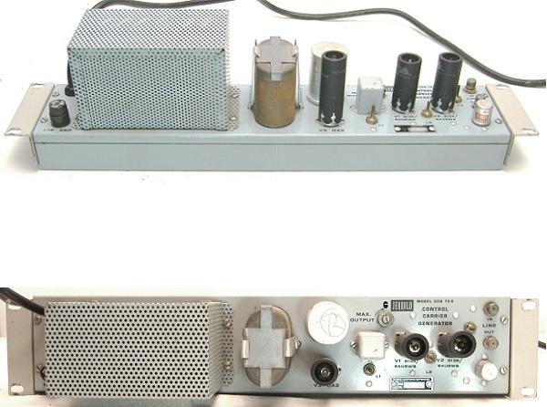
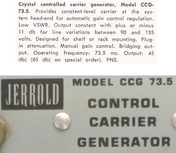
Jerrold Control Carrier Generator
Model CCG 73.5
The Jerrold CCG (Control Carrier Generator) was used in the Headend
to create a RF carrier that would be combined within the channel
spectrum that the AOC (Automatic Overload Control) units would use to
monitor and adjust amplifier signal levels.
The adjustment was necessary to compensate for temperature variations
which altered the cable attenuation characteristics which would cause
the signal levels to change.
The generated signal was at 73.5 MHz in the guard band between
Channel 4 and 5.
 | | Photo:Lew Chandler |
 | | Photo:Lew Chandler |
 | | Photo:Lew Chandler |
Jerrold Electronics Instruction Sheet
Jerrold Control Carrier Generator Model CCG-73.5 series 2 1966
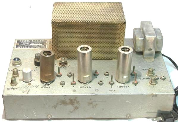
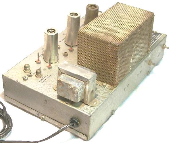
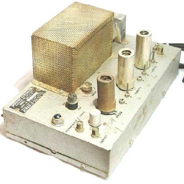
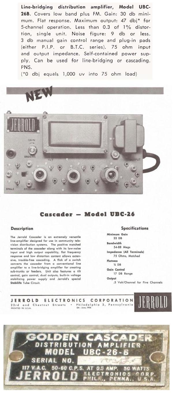
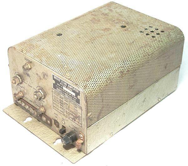
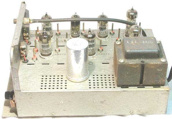
Jerrold Golden Cascader Distribution Amplifier
Model UBC-26-B
The Golden Cascader was the same unit as the AOC Cascader without
the built in AOC circuit. It was called �Golden� because of the golden
color of the mesh cover for the power transformers.
 | | Photo:Lew Chandler |
 | | Photo:Lew Chandler |
 | | Photo:Lew Chandler |
 | | Photo:Lew Chandler |
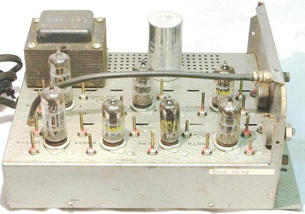
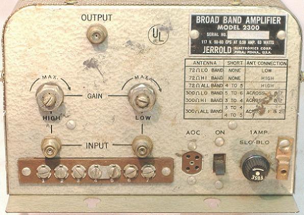
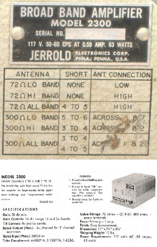
Jerrold Broad Band Amplifier
Model 2300
During the mid 1950s Jerrold fell a little behind other vendors because
they only had low VHF amplifiers available.
With the introduction of Public Television and locally originated
information channels more and more operators were looking to expand
their line ups into the high VHF spectrum. At this time the FCC was also
exploring opening up the UHF bands for broadcast TV use. This would
require Cable TV operators to expand their channel offerings even more.
Other manufacturers were offering 2 types of 12 channel amplifiers. For
example Blonder Tongue offered the MLA series split band 12 channel
amplifier and Spencer Kennedy Labs offered the 212TV 12 channel
distributed amplifier.
In response Jerrold developed its own 12 channel amplifier designs for
the growing need. The first split band 12 channel design was the Model
2300. The 2300 was a very versatile design using an input jumper
setup which allowed the operator to input separate high channels,
separate low channels or all channels depending on the need.
The amp was a very successful design and was used as a Headend
combiner amplifier, a distribution amplifier in large systems and both a
mainline amp and a distribution amp in small systems. The 2300 was
later upgraded to the 2300A and production continued into the 1960�s.
 | | Photo:Lew Chandler |
 | | Photo:Lew Chandler |
 | | Photo:Lew Chandler |
 | | Photo:Lew Chandler |
 | | Photo:Lew Chandler |
Jerrold Electronics Instruction Sheet
Jerrold Broadban Distribution Amplifier Model 2300 1961
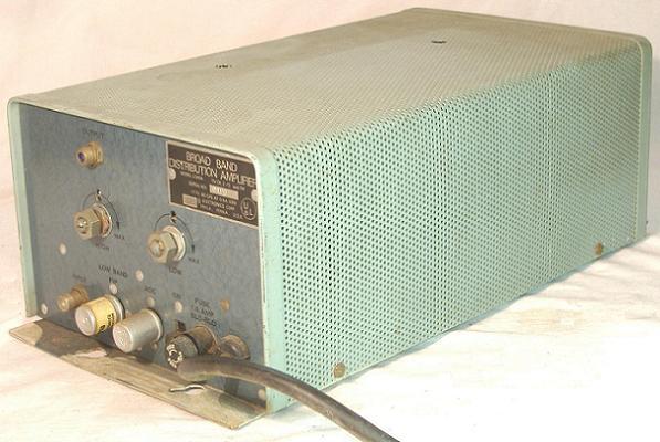
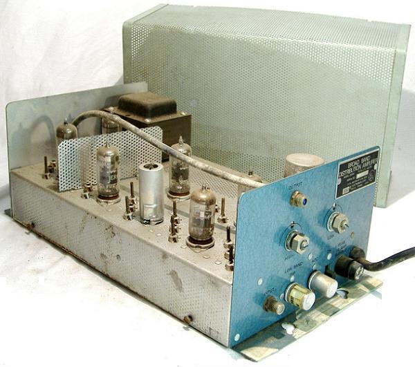
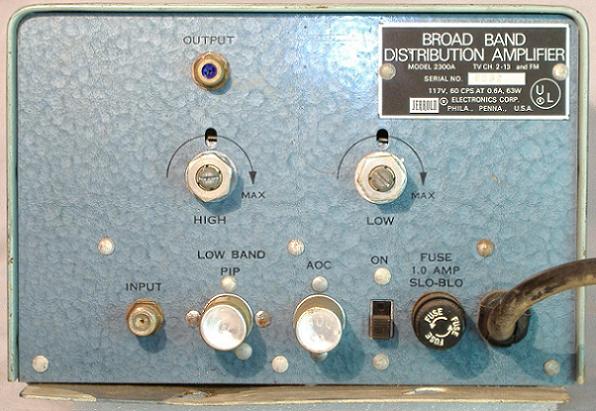
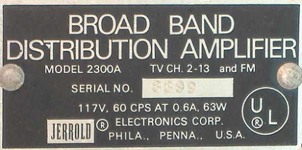
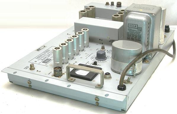
Jerrold Broad Band Distribution Amplifier
Model 2300A
 | | Photo:Lew Chandler |
 | | Photo:Lew Chandler |
 | | Photo:Lew Chandler |
 | | Photo:Lew Chandler |
Jerrold Electronics Instruction Sheet
Jerrold Broadban TV-FM Amplifier Model 2300-A 1964
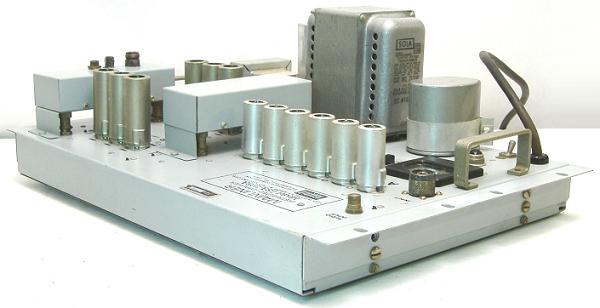
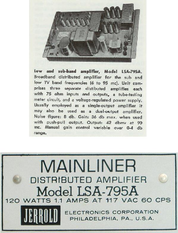
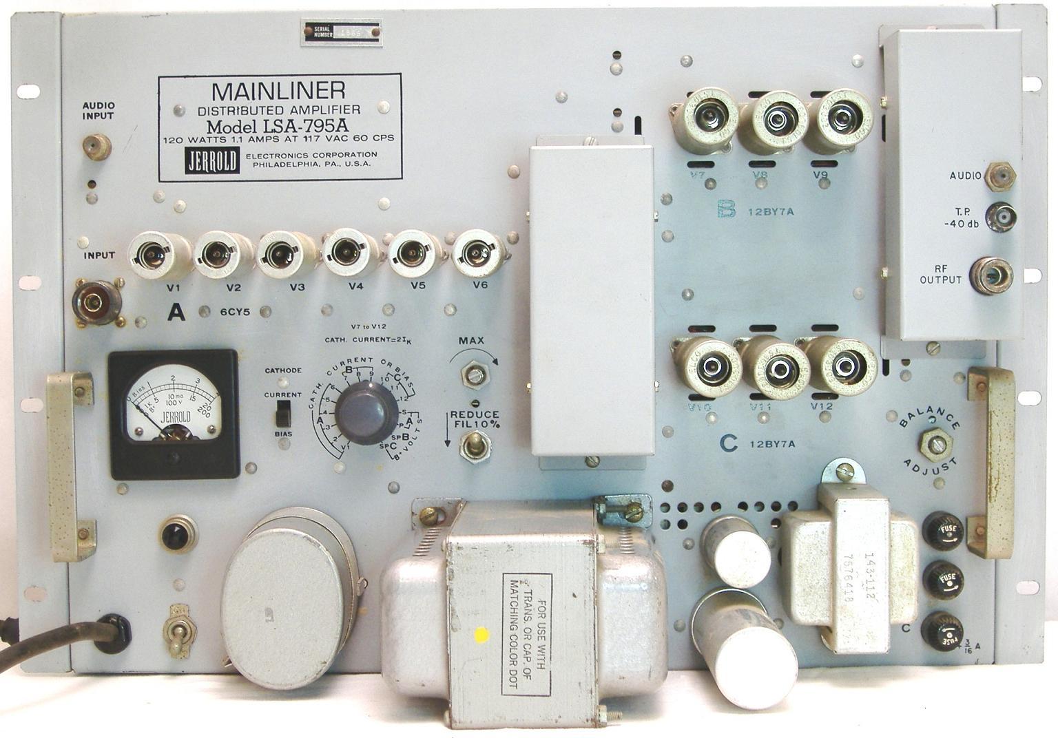
Jerrold Mainliner Distributed Amplifier
Model LSA-795A
Donated by Graham Stubbs
Jerrold also developed a Distributed 5 channel low VHF amplifier. The
Distributed amplifier used concurrent amplification stages that give a
higher gain with a lower distortion characteristic. The stages in the LSA
series are marked A, B and C.
 | | Photo:Lew Chandler |
 | | Photo:Lew Chandler |
 | | Photo:Lew Chandler |
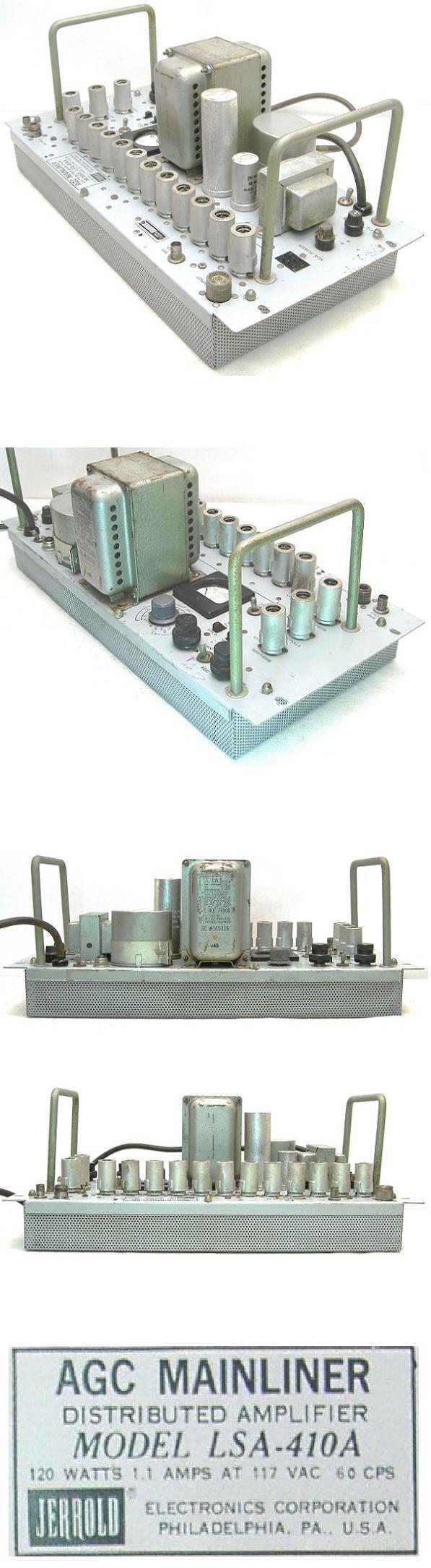
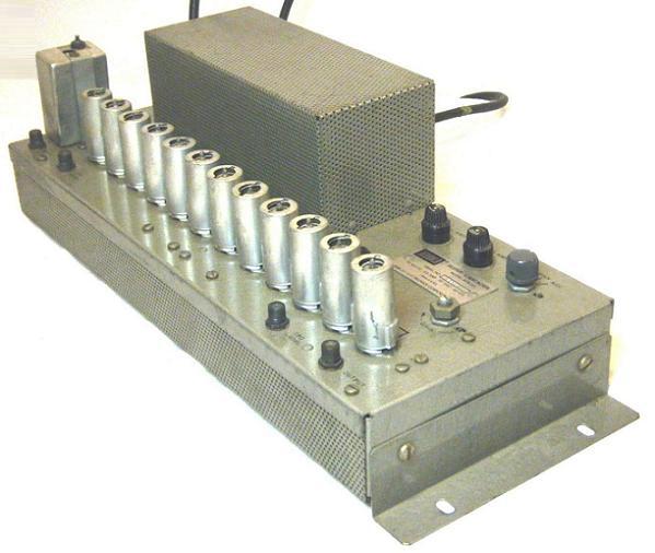
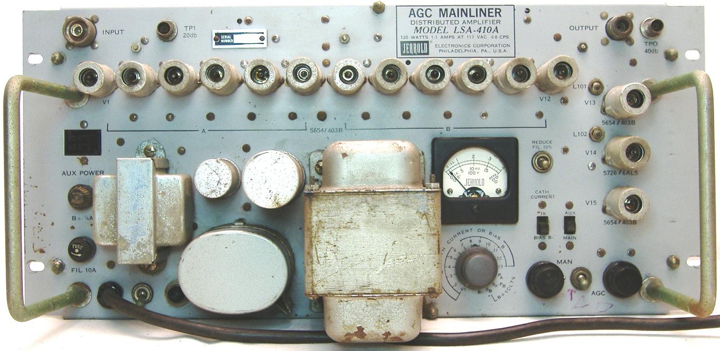
Jerrold Mainliner Distributed Amp
Model LSA-410A
 | | Photo:Lew Chandler |
Jerrol LSA-410A And LSA-410B Distribution System Manual
Jerrol Distribution System Manual for instalation of
LSA-410A And LSA-410B Distributed Amplifiers
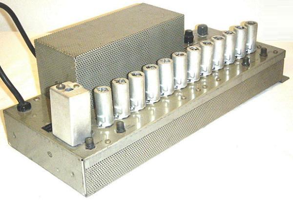
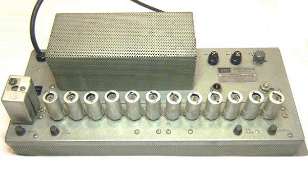
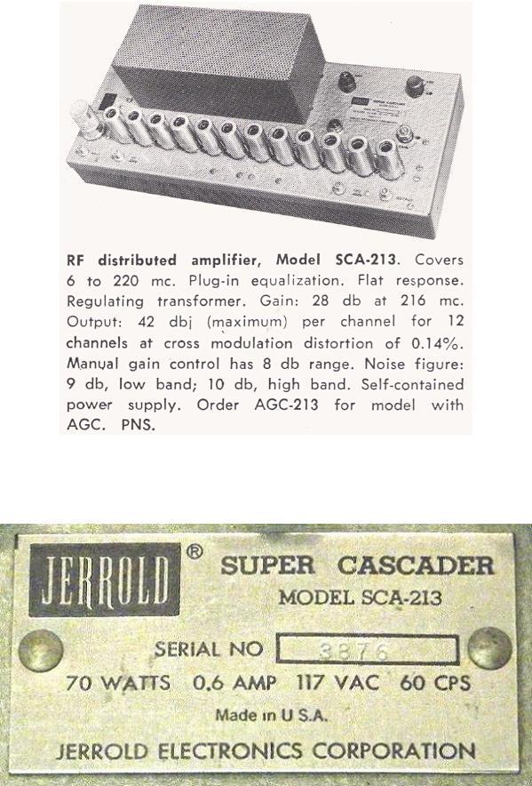
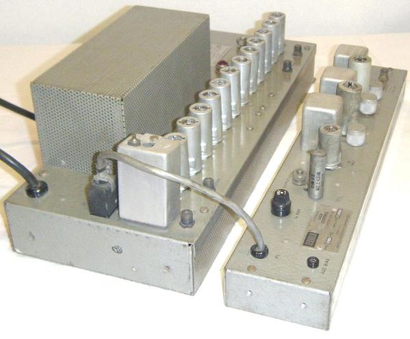
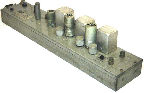
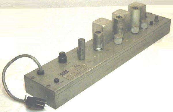
Jerrold Super Cascader Distributed Amplifier
Model SCA-213
Donated by Kaz Majewski, of Centre TV, Wheeling West Virginia
Jerrold incorporated the Distributed design into the Cascader series of
equipment with the introduction of the Super Cascader. There were 2
new additional options that came with the launch of this series of
mainline amplifier.
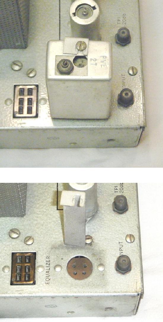
The first was a plug in equalizer so the operator could compensate for
signal loss at specific channels. With the higher gain provided by the
Distributed design longer cable runs could be achieved. The drawback to
this was since higher channels lose more signal than lower channels there
would be an uneven channel response at the input to the amplifier. This
meant the inputs to amplifiers were tilted with channel 2 having more
signal than channel 13. Since the ideal input to an amplifier is flat Jerrold
designed the plug in equalized to compensate for this tilted signal
characteristic.
The second was a separate AGC unit. This gave the operator the option
of placing AGC units where they determined there was a need. The AGC
unit was powered from the amplifier and could be used with other types
of equipment like the PMA amplifier/power supply configuration.
 | | Photo:Lew Chandler |
 | | Photo:Lew Chandler |
 | | Photo:Lew Chandler |
 | | Photo:Lew Chandler |
Jerrold Electronics Instruction Sheet
Jerrold Super Cascader Distributed Amplifier Model SCA-213 1962
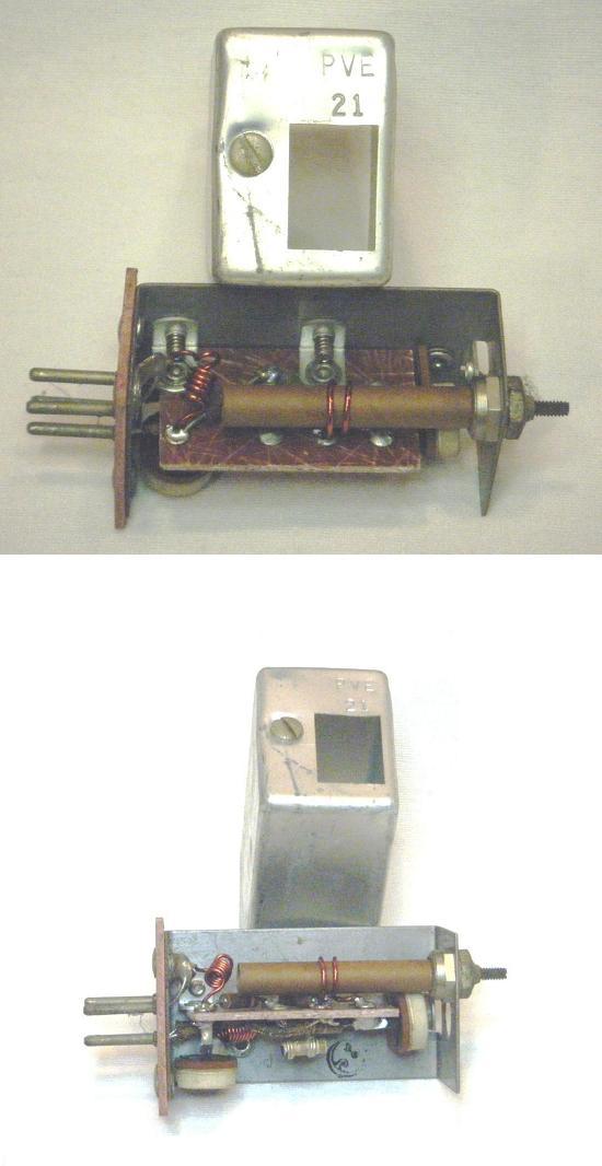
Jerrold Plug In Equalizer
Model PVE 21
Donated by Kaz Majewski, of Centre TV, Wheeling West Virginia
 | | Photo:Lew Chandler |
 | | Photo:Lew Chandler |
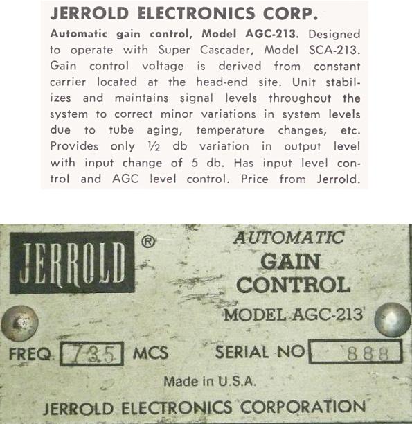
Jerrold Automatic Gain Control
Model AGC-213
Donated by Kaz Majewski, of Centre TV, Wheeling West Virginia
 | | Photo:Lew Chandler |
 | | Photo:Lew Chandler |
 | | Photo:Lew Chandler |
 | | Photo:Lew Chandler |
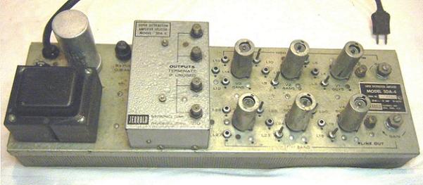
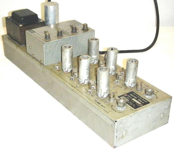
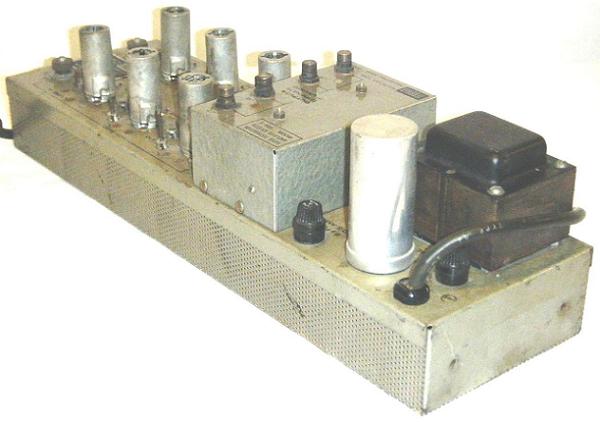
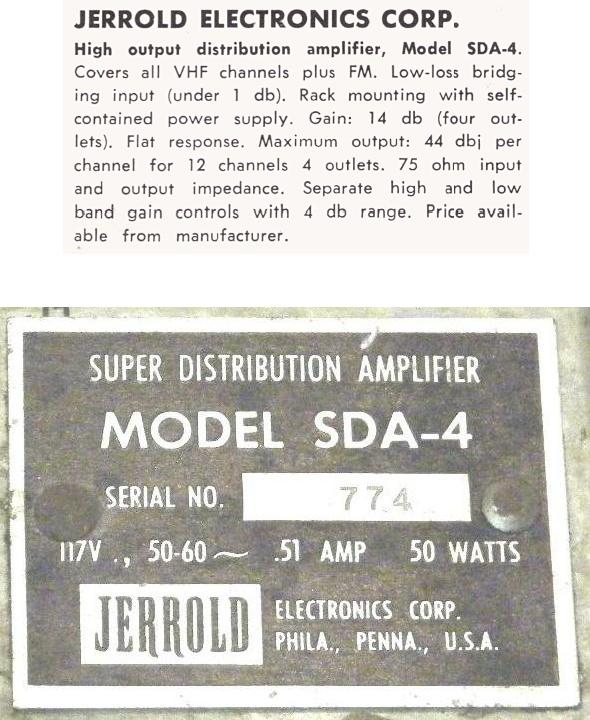
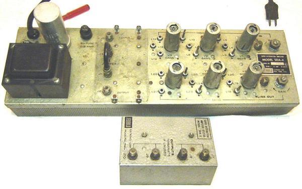
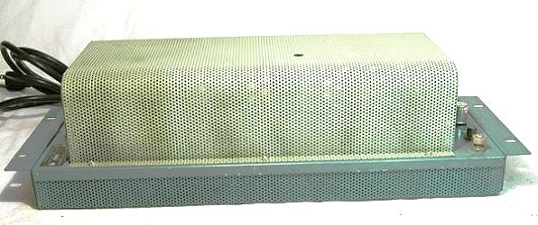
Jerrold Super Distribution Amplifier
Model SDA-4
Donated by Kaz Majewski, of Centre TV, Wheeling West Virginia
The Jerrold SDA-4 Super Distribution Amplifier was the recommended
match for the Super Cascader main line amp. It was similar to the 2300
and had a split band amplifier configuration. The main innovation in the
SDA was the use of a SDA-5 Feedermaker.
With the use of resistive taps becoming standard in Cable Systems the
design of systems changed to use cascading distribution amps. This
meant that multiple outputs could be used to provide signal to multiple
cables going in different directions. These cable runs would have
secondary amplifiers that would add to the distance signal could travel.
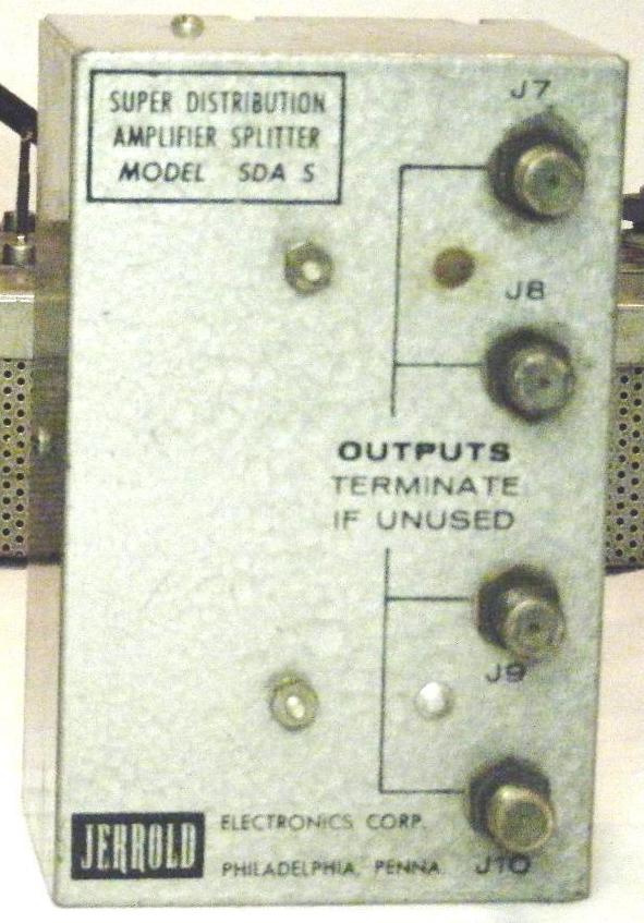
The introduction of the feedermaker allowed the SDA-4 to be configured
to provide signal at 1, 2 or 4 outputs. Thus it could feed signal to 1, 2 or 4
amplifiers farther down the feeder line.
This was the beginning of the bridger amp and the line extender amp
concept developed during the transition to transistorized equipment.
 | | Photo:Lew Chandler |
 | | Photo:Lew Chandler |
 | | Photo:Lew Chandler |
 | | Photo:Lew Chandler |
Jerrold Electronics Instruction Sheet
Jerrold Super Distribution Amplifier Model SDA-4 1962
Jerrold Super Distribution Amplifier Feedermaker
Model SDA-5
Donated by Kaz Majewski, of Centre TV, Wheeling West Virginia
 | | Photo:Lew Chandler |
 | | Photo:Lew Chandler |
 | | Photo:Lew Chandler |
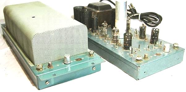
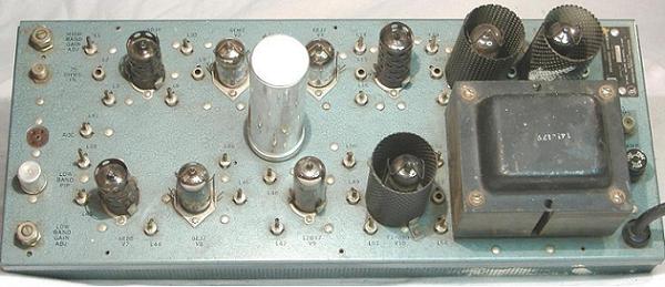
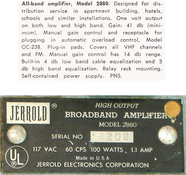
Jerrold High Output Broad Band Amplifier
Model 2880
The Jerrold 2880 was the Jerrold split band main line amplifier and was
used for applications where there was not a need for the Distributed amp.
These were MDU (multi dwelling unit) applications such as campus
areas, trailer parks, small towns and high rise complexes. It was usually
used with the 2300A and the ABD 1A.
 | | Photo:Lew Chandler |
 | | Photo:Lew Chandler |
 | | Photo:Lew Chandler |
 | | Photo:Lew Chandler |
Jerrold Electronics Instruction Sheet
Jerrold 2880 Hi Output Broadfband TV-FM Amplifier 1962
|

