The Old CATV Equipment Museum
CATV Headend Electronics
Amplifiers: Vacuum Tube Broadband Amplifiers
This page illustrates Broadband Vacuum Tube Amplifiers. This amplifier can be characterized as follows:
- Description: Broadband RF distribution amplifier with adjustable gain or AGC circuitry.
- Circuitry: Vacuum tube.
- Intended Installation: Interior locations including headend buildings, attics, basements, and equipment closets.
- Frequency Range: VHF Low Band 54-88 MHz (VHF Channels 2-6). Some models extended below 54 MHZ to include the subband 5-47 MHz (Channels T7-T13).
- RF Ports: One input port and one or more output ports. Earlier models were fitted with 300-ohm screw terminals for use with twinlead in home and MDU applications. Later models were fitted with coaxial connectors for use in CATV headend applications. Some models were equipped with both screw terminals and coax connectors.
- Power Switching: None required, although some amplifiers were fitted with chassis-mounted switches for maintenance purposes. This amplifier was designed for continuous operation.
- Housing: Steel chassis fitted with a perforated metal cover. Most models were fitted with flanges or lugs for permanent installation on a wall or other surface.
These were versatile amplifiers. During the early years of the cable TV industry, they were used as headend launch amplifiers, and for internal distribution within MDUs. Their benefits include the ability to withstand overloads and peak voltages which would be capable of destroying bipolar transistor systems very quickly. This allows these headends to operate for longer periods of time with a reliability comparable to the difference between LCD screens and older model plasma sets.
They also found service in numerous non-CATV applications:
- MDU building owners used them to distribute signals received off-the-air to individual units. One distribution amplifier could serve a 16-unit building; in larger buildings, two or three amplifiers could be cascaded. These amplifiers could be connected to receive signals from a rooftop antenna, a cable TV drop, or master antenna system.
- Schools and institutions used them to distribute off-air and closed-circuit signals to classrooms, offices, and conference rooms. Similarly, hospitals used them to distribute off-air and closed-circuit signals to patient rooms.
- Appliance and furniture stores used them to distribute signals to television-set displays.
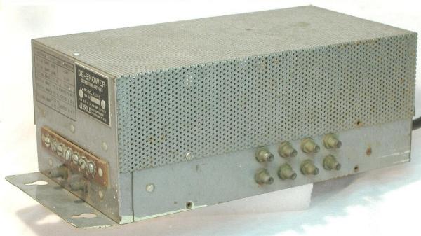
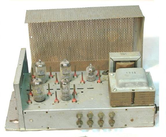
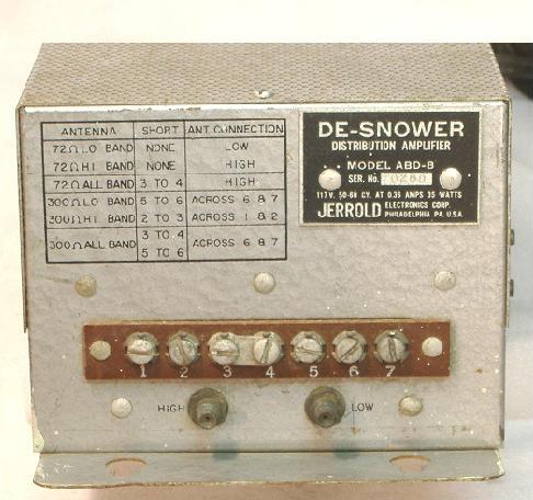
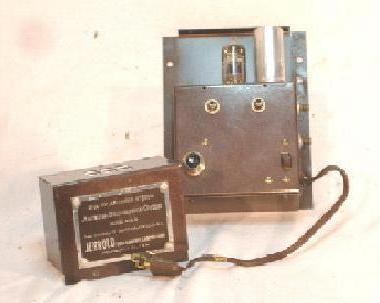
Jerrold Model ABD-8
"De-Snower" Distribution Amplifier
 | | Photo:Lew Chandler | | |
 | | Photo:Lew Chandler | | |
 | | Photo:Lew Chandler | | |
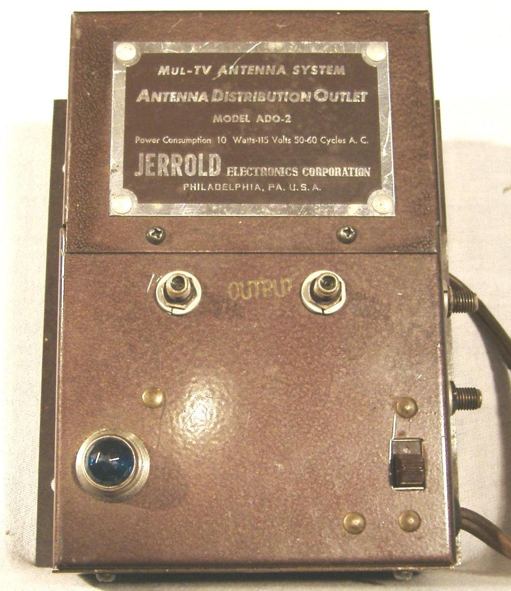
Jerrold Model ADO-2 Antenna Distribution Outlet
 | | Photo:Lew Chandler | High resolution | |
 | | Photo:Lew Chandler | | |
  | | Photos:Lew Chandler | | |
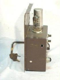
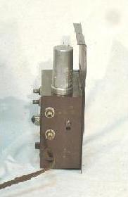
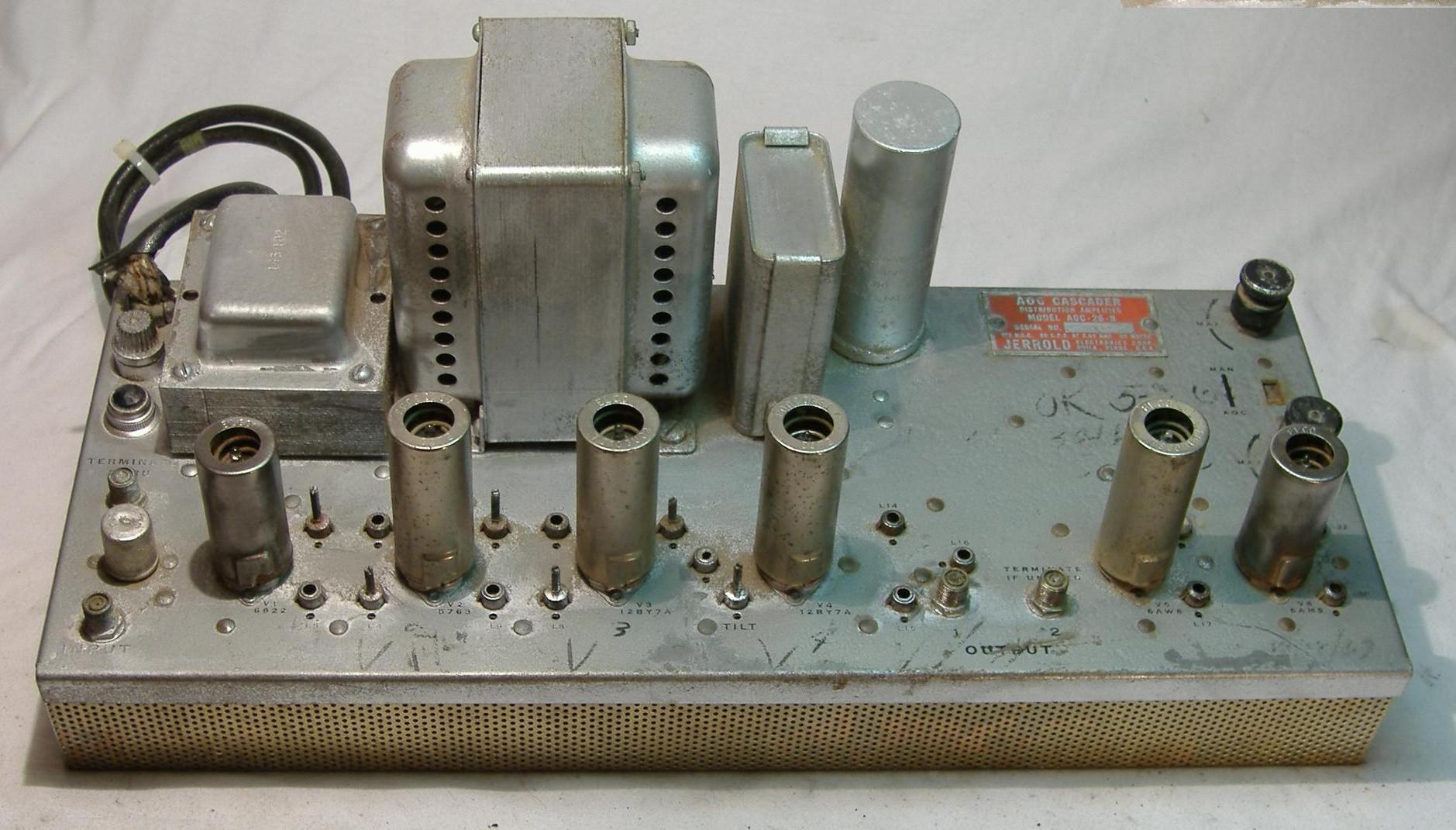
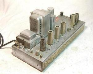
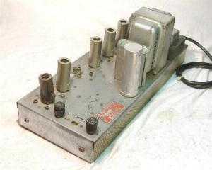
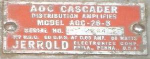
Jerrold Model AOC-26-B
"Cascader" Distribution Amplifier
 | | Photo:Lew Chandler | High resolution | |
  | | Photos:Lew Chandler | | |
 | | Photo:Lew Chandler | |
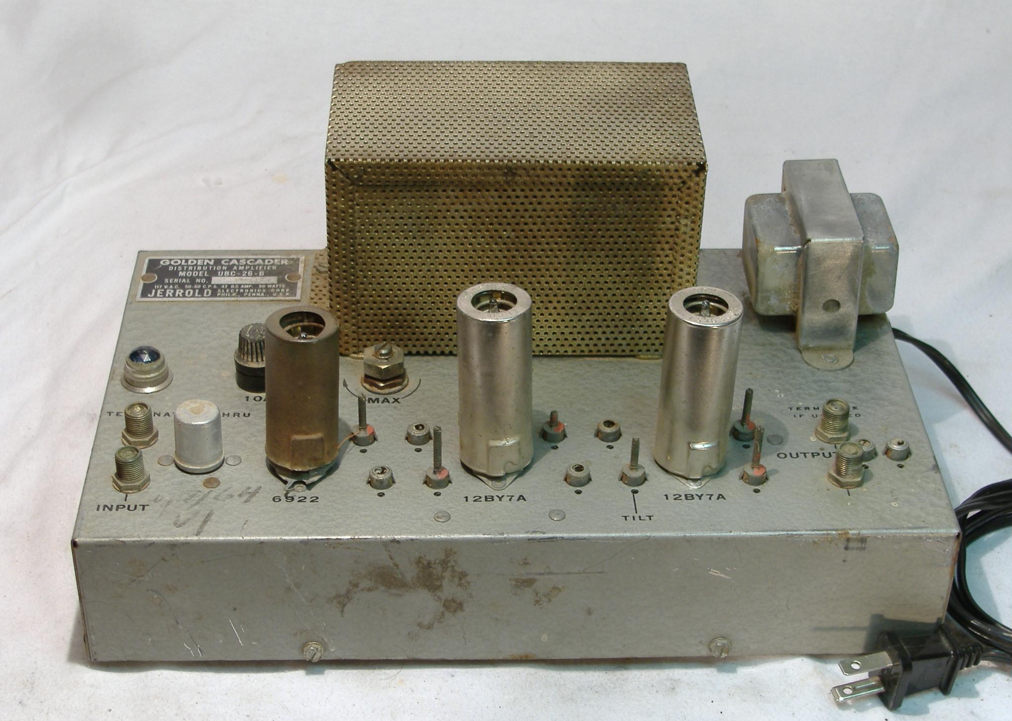
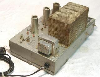
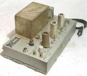
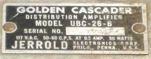
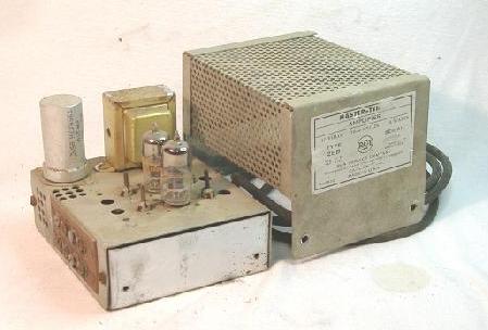
Jerrold Model UBC-26-B
"Golden Cascader" Distribution AmplifierThis amplifier was also known as the "uniband" amplifier. It was designed to amplify the frequency band 5-88 MHz. This band includes the VHF low band (VHF Channels 2-6) and the subband (cable Channels T7-T13).
 | | Photo:Lew Chandler | High resolution |
  | | Photos:Lew Chandler | | |
 | | Photo:Lew Chandler | | |
RCA Model 2bb Revision 2
"Master Tenna" Amplifier
 | | Photo:Lew Chandler | | |
  | | Photos:Lew Chandler | | |
 | | Photo:Lew Chandler | | |
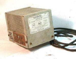
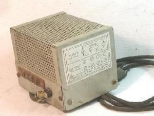
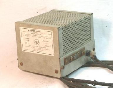
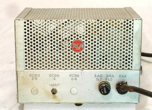
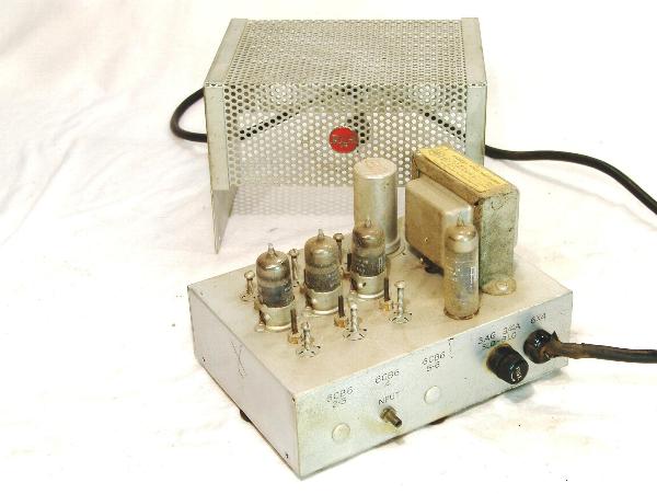
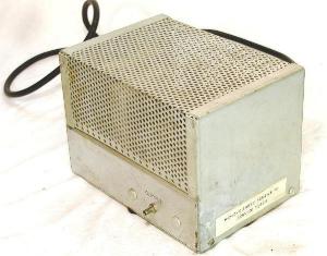
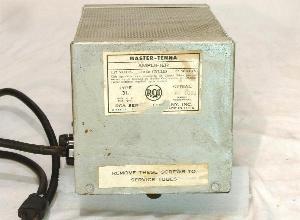
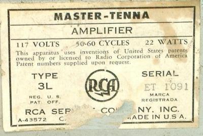
RCA Model 3L "Master-Tenna" Amplifier
 | | Photo:Lew Chandler | | |
 | | Photo:Lew Chandler | | |
  | | Photos:Lew Chandler | | |
 | | Photo:Lew Chandler | | |
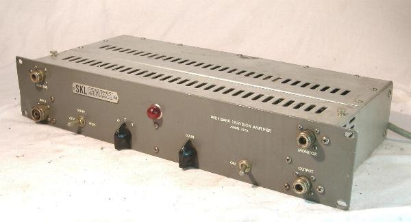
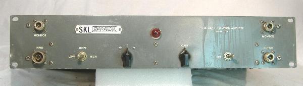
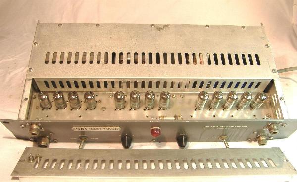
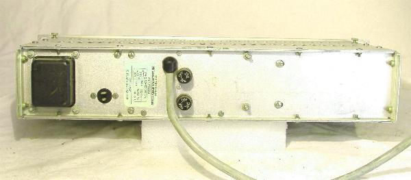
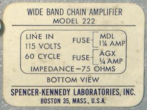
Spencer-Kennedy Laboratories
Wide Band Chain Amplifier Model 222
 | | Photo:Lew Chandler | | |
 | | Photo:Lew Chandler | | |
 | | Photo:Lew Chandler | | |
 | | Photo:Lew Chandler | | |
 | | Photo:Lew Chandler | | |
|